By Richard VK5ZLR
Low cost variable frequency GPS locked reference
- Provides GPS locked frequency anywhere between 1 Hz and 16 MHz.
- Allows 1nSec phase resolution.
- Cost $25.
The unit consists of low cost Chinese (Ebay) modules, free software and a small homebrew interface cable.
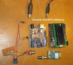
Comprising:
Arduino UNO board . Approx $5
Robot LCD arduino shield Approx $5
Ublox NEO7 GPS module Approx $14
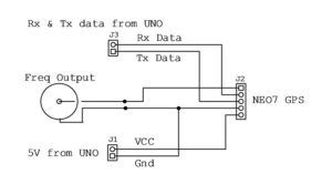
Small homebrew harness, no cost
Software , no cost.
LCD shield:
UNO:
GPS:
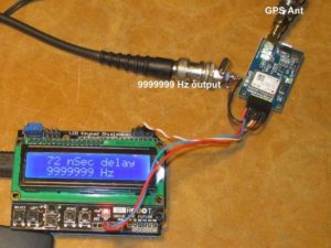
The NEO7 modules have the built in capability to have the PPS output rate varied from 1PPS to approx 16 MHz.
The output freq is kept on track internally in the NEO7. The arduino sends the appropriate UBLOX control command to the NEO7, the display enables the operator to see the output frequency and adjust it using the buttons. The phase is likewise adjustable.
All serial communication is 9600 baud, as this is the default GPS module baud rate
The resulting waveform is pretty rough, as it is derived form a square wave, and it has measurable jitter as the NEO7 applies freq corrections.
The waveform is not really suitable for use as a LO or mixer input in a radio, because of this phase noise.
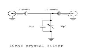
Although Tom, VK5ZTS used it as an injection source in a 6801 Codan, and it did prove satisfactory. A simple two-pole xtal filter will tidy up the waveform, and make a nice sine wave output, but it is only good on one freq.
Nevertheless, for reference and alignment of test gear and radios the waveform is good enough.
The s/ware retains the latest freq & phase settings in EEPROM, so it reverts to the last used parameters on boot up.
The project lends itself to being packed into a small project box with a 9v battery for field use. For indoor use an external 3.3v active GPS antenna is required. These are about $3 off Ebay.
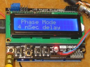
The select button toggles between Freq and Phase entry mode.

The up and down buttons increment/decrement the freq & phase.
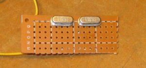
A optional 10 MHz crystal filter cleans up the 10 MHz waveform nicely.
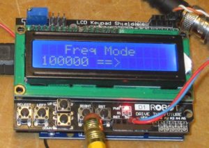
The left & right buttons select the step size.
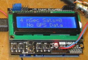
And if there are zero Satellites visible, the unit reverts to an unlocked 1PPS output.
The s/ware can accept new freq and phase data via 9600 baud serial. Using a free terminal program such a Real Term the freq and phase info can be entered by computer keyboard, in which case the Robot display module is not required.
Firstly disconnect the GPS Serial lines, or the GPS streaming data will conflict with the Serial port data.
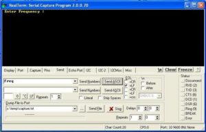
Set the port number, set the Baud rate to 9600, tick the LF box. (linefeed)
Type in freq (lowercase) or phase (lowercase) then Send ASCII.
You will then be prompted to enter the freq or phase data.
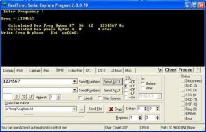
Enter the frequency or phase and Send ASCII, the LCD display will also show the updataed values.
Reconnect the GPS and Reset to pick up the changes.
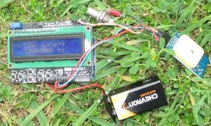
It even works out in the paddock on a 9v battery.
The Arduino C code is free to download from the RASA website here: