By Hayden Honeywood VK7HH
Introduction
As any repeater builder would know, to make a good efficient working repeater requires a lot of time and energy. Performance of a repeater is shown in its ability to provide proper coverage to the intended target audience. Ideally, we want everyone in the target audience to be able to participate in the same conversation, but sometimes not everybody lives within the coverage area of the repeater. To negate this issue we can link multiple repeaters together through various methods to expand that conversation out. This however, usually requires that the users know the correct frequencies, tones and in the case of mobiles, knowing what repeater actually covers the area they are driving thru. What about if we could create a single repeater system that provided coverage over a wider area than could ever be achieved through any one site? How can this even be possible? A little thing called on FM called “the capture effect” helps us out.
The theory
Uh oh… that word. Theory. I would not be at all surprised if you skip over this section of the write-up, but bear with me, it (hopefully) will make sense. Adding multiple receivers on the same repeater input frequency and sending all their audio to a central spot to “vote” which one has the strongest is relatively simple, however having multiple transmitters on the one frequency is a bit more of a challenge. Everyone has heard the classic “doubling” that happens when two stations on FM try to talk over one another. This sometimes can be a mixture of the two signals, usually being garbled and unintelligible. However if one user is stronger than the other, they win, and you can only just hear the other station in the background. This is the “capture effect” at work.
Now, if we transmit the same information, in this case voice at the same amplitude and phase on two or more transmitters, then a station whose receiver is on the repeater channel will automatically “capture” the stronger of the two transmitters. Sounds simple right? Not quite, there is always a catch. The problem lies in the overlap area – that is when you are in “range” of both transmitters and they are within 10 to 15 dB in signal strength of each other at the receiver. If you are in an overlap area and you are hearing two transmitters equally, and if they are not simulcast properly you will get audio distortion, carrier nulling and so on that causes the audio to be unintelligible.
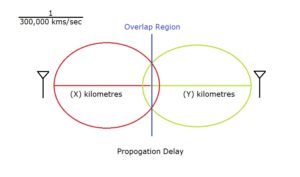
Figure 1. Propagation delay within overlap area
To simulcast on 70cm at least requires very precise frequency control, in order of less than 1 Hz of frequency error. Both transmitters have to be tied to GPS for this level of accuracy. The next problem is the speed of light – it does not go fast enough! This affects the ability for the audio from each transmitter to reach the users receiver in phase. For 10% phase error at 3000 Hz, modulation must arrive at each of the transmitter sites within 10 microseconds of each other. Each one of the transmitters need identical audio response characteristics. We also need the audio to arrive at the users receiver ideally at the same time. Figure 1 demonstrates this. Here we have two transmitters with X and Y distance in kilometres. Ideally we want the received signal within the overlap area to be received at the same time, therefore usually requiring that both X and Y be the same distance. Speed of light travels at 3.3km/microsecond. Anything approaching 100 microseconds of delay starts to get out of phase and distorts, so we need to keep this as low as possible using audio delays.
The biggest problem facing this venture was to build such a system, even just for two sites requires many radios, antennas, feedlines and the list goes on, before we even look at audio delay boards! A commercially produced 2 site simulcast system can commonly cost as much a $200,000! Enter the RTCM/VOTER board powered by the VKLink system.
VKLink and the RTCM/VOTER board
Whilst thinking about ways to expand our coverage on our local repeater system, we had already established a RF based linking system from several UHF 70cm repeaters in the South to the 2m repeater VK7RAA in the North. This worked well, but did have its problems. We needed a better way of linking. Enter the VKLink system.
VKLink was developed by Matt VK3VS and is a “cut down” version of Asterisk PBX, along with app_rpt – a repeater/linking software module that runs on the Raspberry Pi and allows the interfacing to radios via channel drivers. For the purposes of this article we will refer to app_rpt/Asterisk as VKLink. Matt realised this was a good a way of linking repeaters via VoIP with a Raspberry Pi, a radio and a genuine CM108/199 USB sound card FOB. In later developments, Matt included the ability to be able to use the Pi’s GPIO pins for signal switching and any USB sound card for audio. All “nodes” on the system are able to connect to one another, report to a central server and are completely remote controllable – see Figure 2. The whole system works very similar to IRLP and/or Echolink, only much better and more flexible. More information is available at the website – http://vklink.com.au
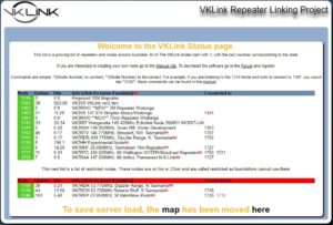
Figure 2. A list of VKLink nodes operating around Australia with real-time status
VKLink also comes with the chan_voter channel driver. This interfaces with the VOTER (Voice Observing Time Extension for Radio) board or RTCM (Radio Thin Client Module). This was developed by Jim Dixon (SK), WB6NIL in 2011 and is available as a user-assemblable (VOTER) or commercially built module (RTCM). Both have the same functionality, but for the purposes of this article, we will refer to it as the VOTER board. Briefly, the purpose of this board is to interface to a repeater (receiver and/or transmitter), send as a data stream audio, and GPS time stamped data in 20mS increments to a central server repeater controller (VKLink). The server analyzes all these data streams (there is potential for hundreds on any particular system) and “votes” which one has the best Signal to Noise ratio. The server then sends the currently best-voted signal back to one (or more) of the specified transmitters.
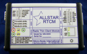
Figure 3. Commercially available RTCM
As the RTCM was slightly out of my price range, I decided on building several of the VOTER boards. I had some PCBs made commercially for a very reasonable price using the open source gerber files and parts ordered. Each board took around 5 hours to populate. Out of the box, these units work fine for voting with no modification needed. The PIC that runs everything is clocked by a 9.6MHz crystal, which is only 25ppm stable, meaning that at this frequency we could potentially see a variation of +/- 240 Hz. This unfortunately is not stable enough for synchronization of the audio and generation of CTCSS tones (if required) so that they are all in phase among multiple transmitters.
Jim WB6NIL said it was impossible to get the PIC to clock to 10MHz through coding. Another ham in the United States (Joe, KC2IRV) had been undertaking the same project, and he suggested using some 9.6MHz oven controlled crystal oscillators (OCXO) sourced from eBay. I built a small board to allow small frequency adjustments (within 1Hz) using a voltage control pin on the OCXO and tested on the bench. In the meantime, KC2IRV had been field-testing these and had determined that even though they were a vast improvement over the standard crystal, CTCSS warble in particular was detectable in the overlap areas due to wandering of the OCXO in frequency. He went about designing a PLL board, which was originally part of a Motorola MSF5000 station. The result was a 10MHz (GPS) signal in, which divides down to lock the 9.6 MHz OCXO in the VOTER boards with the clock reference being tied to GPS and not wandering in frequency, providing a very stable solution.
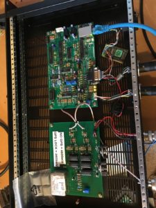
Figure 4. PLL board on left with 9.6 MHz OCXO. My built VOTER board on right
This modification on the board is not required for simple voting operation.
Making it work using the KL series of radios
As I had a quantity of the Unilab/Stanillite series of radios, I went about modifying them for this purpose, starting with the standard mods. It is almost mandatory using the same model radio when voting, and especially so for simulcast. The KL uses a 12MHz reference as standard. I wanted this to work using a 10 MHz reference from the GPSDO. Luckily the KL uses a MC145146 PLL and it is trivial to modify some values in the data once generated by the UNIPROG software to divide down and work with 10 MHz. There is more information on this on my blog website. 12MHz TCXO is removed and replaced with a short piece of RG174 in the PLL compartment of the receiver. The coax runs to a connector of choice on the back of the receiver module just above the header. I used an old MCX connector from spares.
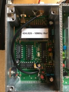
Figure 5. PLL compartment of the KL receiver
The VOTER board needs unfiltered discriminator audio from the receiver. The radio provides a discriminator tap off point, but testing this proved flakey, my guess is there was high-end roll off. Instead, I took it directly from the detector output of the TK10420 discriminator IC.
If simulcasting, the audio need to go to the exact same point on each transmitter. I found it a good idea to sweep the audios and plot them on a graph to make sure they are the same, as any differences in response will be audible in the overlap areas.
Results
The system is currently a two-site simulcast and voted repeater. Performance has been rather impressive with coverage now extending out on one frequency. Through changing the audio timing within each individual transmitters VOTER board, antenna patterns or differing power levels allows experimentation and improvement in overlap areas. So far, I have observed some level of distortion in overlap areas; however, the audio is still completely intelligible. One thing to note with simulcast is you will never get it perfect in overlap. You might fix one area, but then the problem pops up elsewhere.
Repeaters voting is available in real time through the VKLInk AllMon page as shown in Figure 6. As far as I am aware, this is the only simulcast amateur repeater in VK.
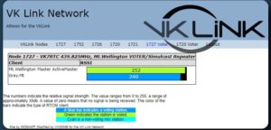
Figure 6. Live RSSI data is viewable from each site
Conclusion
Plans for the future involve expanding the coverage of the 70cm UHF repeater system to include even more sites, moving a 6 metre repeater to simulcast using frequency offsetting due to the longer wavelength involved and add multiple voting sites to a 10 metre repeater.
A follow up article will be published shortly on the VKLink system. For more information on VKLink go to: http://www.vklink.com.au.